8+ boundary diagram
Blocks within the boundary are under control of the Analysis team. Other none more business.
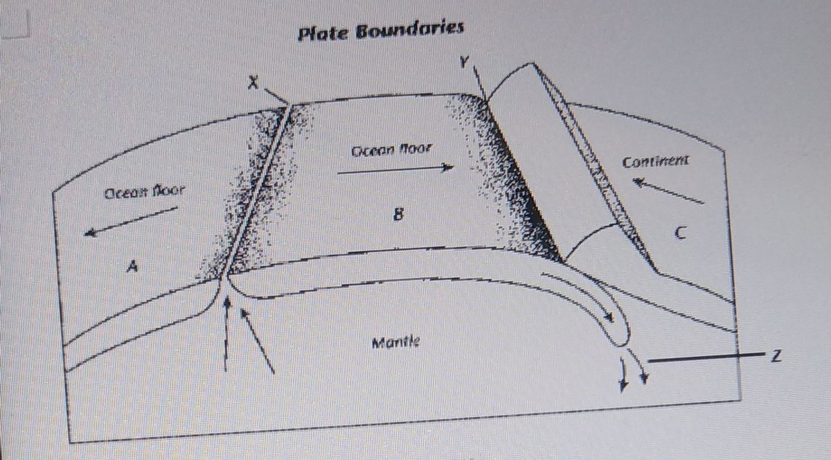
Answered I Which Type Of Plate Boundary Occurs Bartleby
Resize a System Boundary shape.
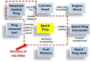
. In this brief tutorial well show you how to add boundaries to your XMind mind maps. A boundary diagram represents all the interfaces of a system in the form of a block diagram. The transformation of the inputs into the outputs.
You can edit this. It distinguishes the border between use cases and actors use cases are inside the borders of the system. A boundary diagram is a graphical illustration of the relationships between the subsystems assemblies subassemblies and components within the object as well as the interfaces with.
The FedRAMP Project Management Office PMO Third-Party Assessment Organizations 3PAO and agency assessors will be at a minimum looking for three diagrams. The noise factors that affect the system. System Boundary Diagrams sometimes come up in the context of a Use Case and sometimes in the context of Software Testing.
Either way they are a useful in the effort. It is the useful introduction to aFMEA as the functions of a system along with the failures are. Select the shape and then drag a.
System Boundary Diagram classic Use Createlys easy online diagram editor to edit this diagram collaborate with others and export results to multiple image formats. Copy of BOUNDARY DIAGRAM. Better System and FMEA Design with Block Diagrams The FMEA steps such as defining the scope developing system structures and functional analyses are more.
The control factors the. In a use case diagram the system boundary is a boundary surrounding the use cases which indicates the system. A boundary diagram defines the scope of system design or analysis to be included in the project charter.
The P diagram parameter diagram is used to prepare an FMEA. It also defines the most important external interfaces that must be considered. Boundary - generally a dashed line rectangle that defines the scope for the DFMEA within the boundary.
Use Createlys easy online diagram editor to edit this diagram collaborate with others and export results to multiple image formats. For more mind mapping templates tutorials and training visit http. The system boundary box must be the first element placed in a use-case diagram.
The Authorization Boundary Diagram is a visual representation of the components that make up the authorization boundary by defining the authorization boundary for the CSO.

Professional Articles Block Diagram Fmea Boundary Diagram Dietz Consultants

Radiation Induced Absorption Of The Pet Films Obtained From Figure 4 Download Scientific Diagram

The Histogram Of Parameters Of The Boundary Condition In A Learning Download High Resolution Scientific Diagram
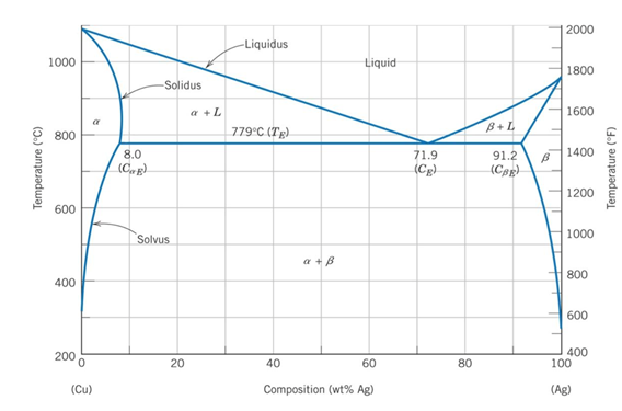
Solved Consider The Phase Diagram Of Ag Cu Given That Chegg Com

Professional Articles The Boundary Diagram Better System And Fmea Design With Block Diagrams Dietz Consultants

Diagram Of The Boundary X 2 T 2 8 ŋ Ab X N 8 And T N 8 ŋ Bc Download Scientific Diagram
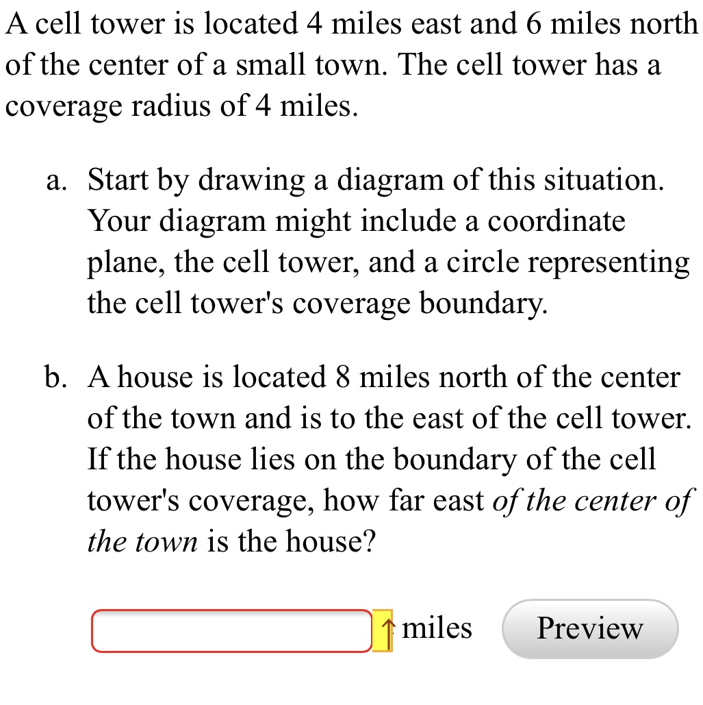
Answered A Cell Tower Is Located 4 Miles East Bartleby
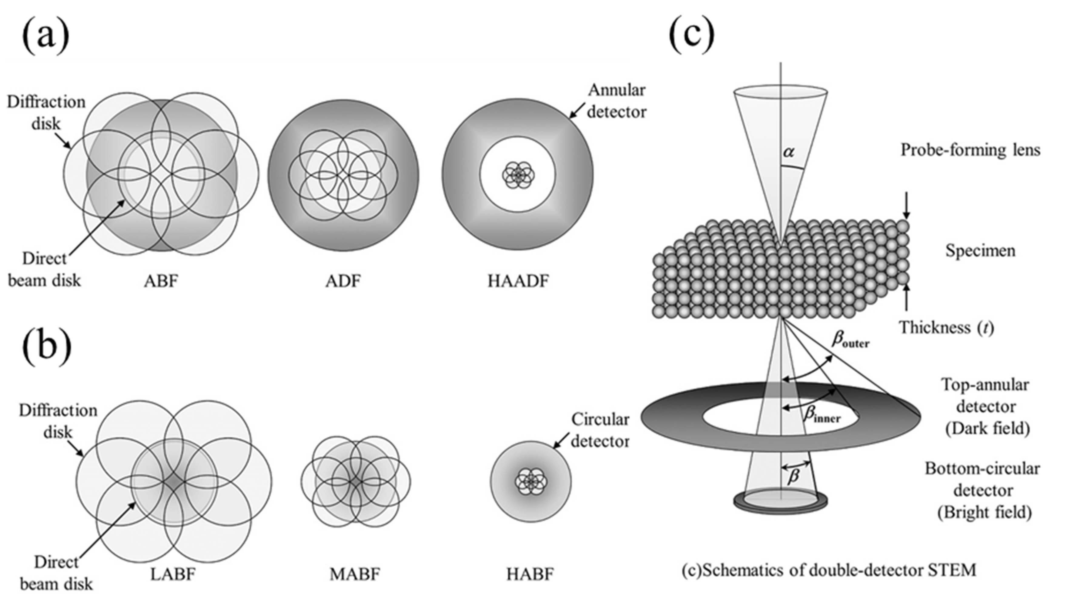
Crystals Free Full Text A Review Of Grain Boundary And Heterointerface Characterization In Polycrystalline Oxides By Scanning Transmission Electron Microscopy Html

Nuclear And Electronic Stopping Power For Interactions Between Neutral Download Scientific Diagram
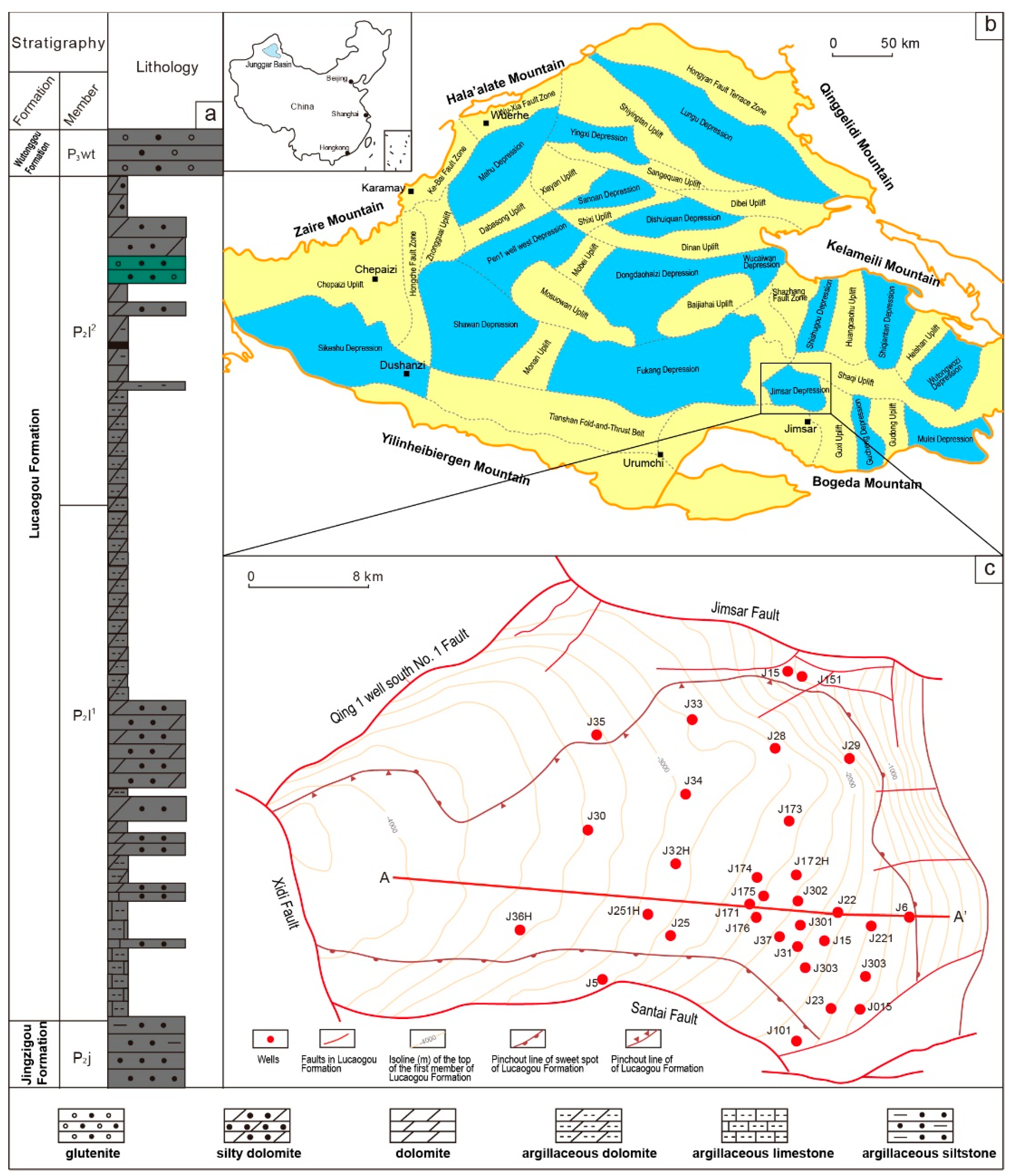
Energies Free Full Text Geochemical Characteristics And Process Of Hydrocarbon Generation Evolution Of The Lucaogou Formation Shale Jimsar Depression Junggar Basin Html

Boundary Diagram Block Boundary Diagram Template

Fmea Q And A Fmea Boundary Diagram
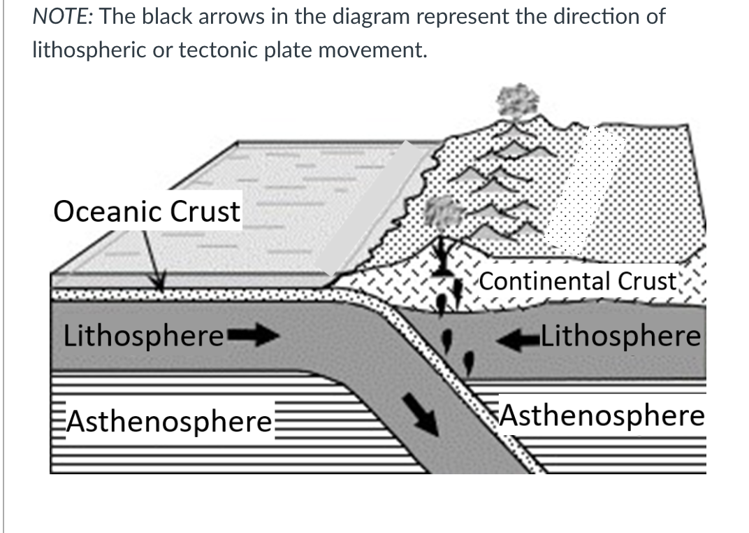
Answered Which Plate Tectonic Boundary Is Bartleby
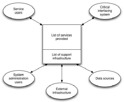
File System Boundary Diagram Png Wikimedia Commons

Professional Articles Block Diagram Fmea Boundary Diagram Dietz Consultants

Engn2225 Oc System Boundary Chart Youtube
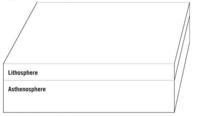
Chapter 3 Problem 9lr Bartleby